DIVISEURS POUR SSPA 144MHz
VHF power splitter .
Pour coupler plusieurs amplificateur SSPA, voici un module permettant de diviser la puissance venant du transceiver pour la répartir vers ceux-ci.
Dans notre cas, le problème consiste à coupler 3 modules amplificateurs.
Pour ce splitter il faut :
- Des pertes faibles
- Une isolation correctes entre les voies de sortie.
- Des rotations de phases équivalentes sur les trois sorties. Ceci est très important pour le couplage des amplificateurs.
- Une puissance admissible de 15 Watts environ.
This module is designed to provide the drive for an high power SSPA having 3 amplifiers combined .The output combiner is an ‘’in phase type’’ consequently the input splitter outputs have also to be in phase.
Target specifications: All ports terminated to 50 Ohms.
- Low loss : < 0.3 dB
- Output phase variation between ports : < 5°
- Isolation between outputs : > 25 dB
- Maximum input power : 15 Watts
Le schéma
Schematic
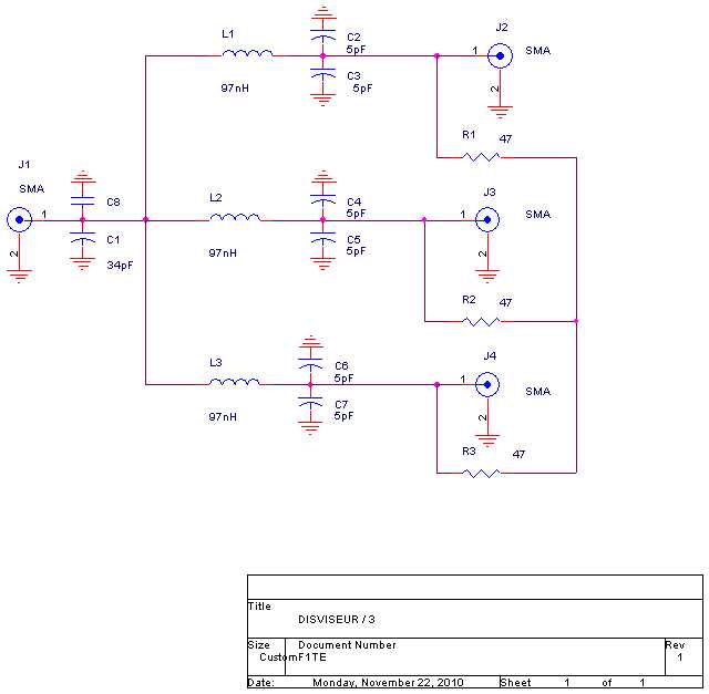
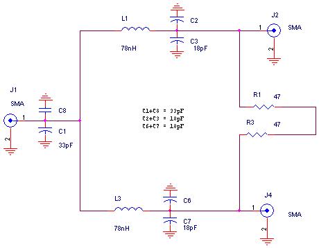
Les condensateurs sont tous des CMS en 0805
L'ensemble C1/C8 doit faire 34 pF. Demême pour les condensateurs C2/C3, C4/C5 et C6/C7 qui doivent faire 10 pF.
Les résistances de 47 Ohms sont des VISHAY PR03 de 3W
Les selfs de 97 nH sont réalisées en fil émaillé de 7 ou 8/10 mm, 5 tours sur un diamètre de 6 mm et une longueur d'environ 6 mm.
All capacitors are 0805
C1+C8 should be 34pF
C2+C3 should be 10pF
C4+C5 should be 10pF
C6+C7 should be 10pF
All 47 Ohms resistors are : 3 Watts WISHAY PR03
The 97 nH inductances are made as follow: 0.8 mm enamelled wire, 5 turns diameter 6mm, length 6mm.
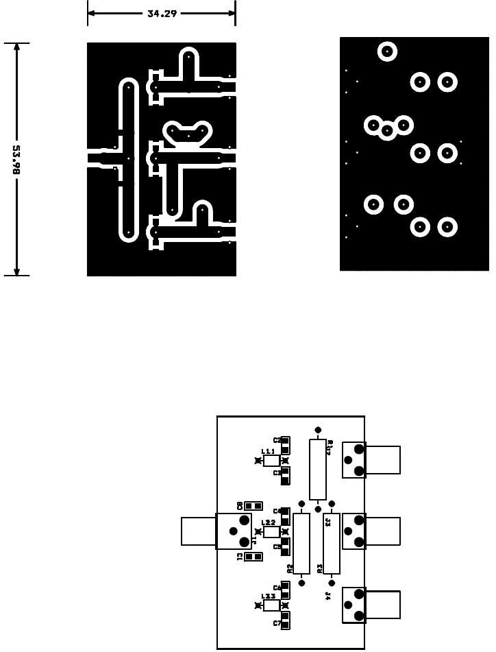
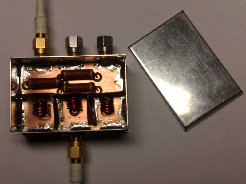
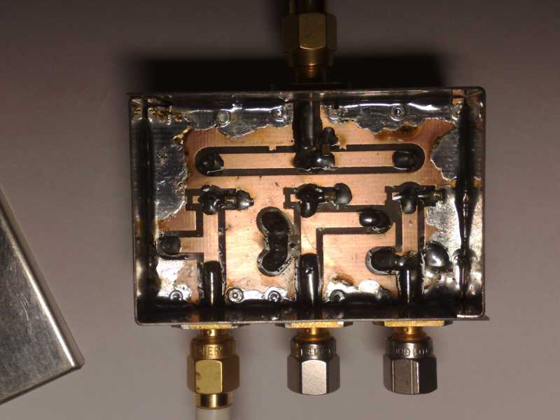
La réalisation est faite sur un circuit imprimé double faces, soudé dans un boîtier Shubert 35 x 55x 30 mm.
Les selfs sont isolée par du feuillard de cuivre pour éviter un couplage magnétique entre elles.
Splitter module is made of a double side PCB soldered on a 35 x 55 x 30 mm ‘’Schubert’’ metal box.
Copper foil soldered on the PCB and the box are used to prevent mutual coupling between the inductances.
L'optimisation se fait au VNA en jouant sur l'écartement des spires des selfs.
Chaque sortie est à -4.88 dB par rapport au niveau d'entrée, pour 4.77 dB théorique.
L'écart de phase entre chaque sortie est de l'ordre du degré.
L'isolation entre les sortie est de 28dB
Tuning for best RF performances is made with the help of a VNA by slightly modifying the shape of the inductors.
Each outputs have been measured around –4.88 dB relative to the input , very close to the theoretical value of –4.77 dB.
Phase difference between the outputs is in the range of 1 to 2°.
Isolation between ports better than 28dB.
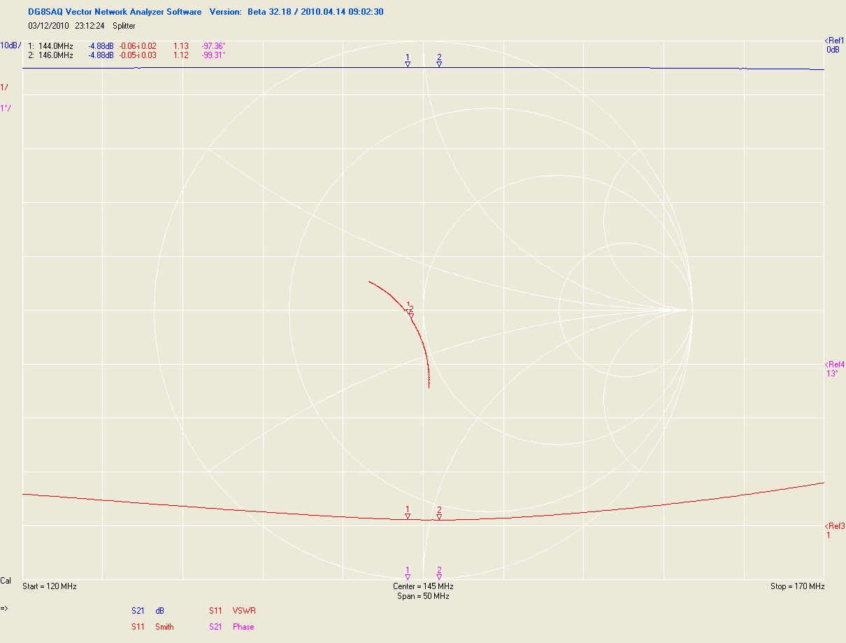
Above results are obtain with a 50 Ohm input generator and 50 Ohms load on each output .
When the splitter is used between a transceiver and amplifiers it is recommended to tune carefully the input impedance of each amplifiers also to 50 Ohms . It would be very nice to use an isolator between the transceiver and the input of the splitter. VHF isolator can be found very often on flea markets coming from old VHF networks , they usually have built-in variable capacitors for tuning on 2M.
DIVISEUR PAR 2
Me même principe peut être utilisé pour faire un diviseur par deux.
Le schéma est le suivant :
Le même circuit imprimé peut être utilisé en ne câblant que les deux voies extrêmes.